building bidirectional serial communication between nexys board and gui

building bidirectional serial communication between nexys board and gui
1. Introduction
Introduction:
The purpose of this project is to building bidirectional serial communication between nexys board and gui. The nexys board will be used to control the position of a servo motor, and the GUI will be used to display the position of the servo motor in real-time. In order to accomplish this, the following hardware and software will be used:
– Nexys board
– PmodRS232
– PmodJSTK2
– Xilinx ISE 14.7
– Tera Term
The PmodRS232 will be used to establish the serial communication between the nexys board and the computer. The PmodJSTK2 will be used to control the position of the servo motor. The Xilinx ISE 14.7 software will be used to create the necessary HDL code, and Tera Term will be used to communicate with The Nexys Board Via The Serial Port.
The project will be divided into the following sections:
– Hardware setup
– HDL code development
– Tera Term configuration
– Testing and results
Hardware Setup:
The first step is to connect the PmodRS232 to the nexys board. The PmodRS232 has four pins:
– TXD: Transmit data
– RXD: Receive data
– GND: Ground
– VCC: +5V power
The PmodRS232 will be connected to the nexys board as follows:
– TXD to pin B13
– RXD to pin B14
– GND to pin B15
– VCC to pin B16
The next step is to connect the PmodJSTK2 to the nexys board. The PmodJSTK2 has four pins:
– X: Analog input for X-axis
– Y: Analog input for Y-axis
– GND: Ground
– VCC: +5V power
The PmodJSTK2 will be connected to the nexys board as follows:
– X to pin B
2. Hardware and software requirements
In order to build a bidirectional serial communication between the nexys board and the GUI, you will need the following hardware and software requirements:
• Nexys 4 DDR Artix-7 FPGA Trainer Board
• USB cable
Serial cable
• Vivado WebPACK™ Design Software
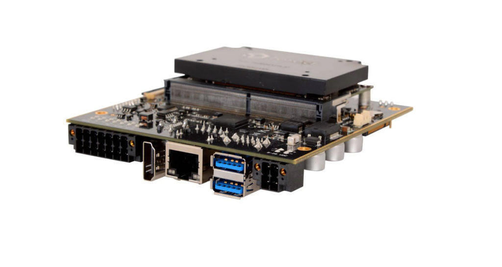
The Nexys 4 DDR Artix-7 FPGA Trainer Board is used to develop and test cutting edge designs incorporating the newest Artix-7 FPGA technology from Xilinx. The board features an Artix-7 FPGA with 12,600 logic cells, integrated USB-JTAG programming and debugging support, integrated USB-UART bridge, and on-board memory resources. The Nexys 4 DDR is also equipped with a number of peripheral devices, including a 16×2 character LCD, 4-Digit 7-Segment Display, VGA Output, Audio Codec, SD Card Socket, and 2 Pushbuttons.
The USB cable is used to connect the board to the computer. The serial cable is used to connect the board to the serial port on the computer. The Vivado WebPACK Design Software is used to program the FPGA.
3. Step-by-step guide
Introduction:
In this blog, we’ll be discussing how to set up bi-directional serial communication between a Nexys board and a GUI. This can be useful for debugging purposes, or for sending and receiving data in real-time. We’ll be using the Pmod USBUART for this purpose.
First, let’s take a look at the hardware that we’ll need:
– A Nexys board
– A Pmod USBUART
– A USB cable
Now that we have all of the hardware that we need, let’s get started!
1) Firstly, we need to connect the Pmod USBUART to the Nexys board. Make sure to connect it to the correct set of pins (refer to the datasheet for more information).
2) Next, we need to open up the Vivado project that we’ll be using. In the project, we need to add the Pmod USBUART IP core. This can be done by going to Project -> Add IP.
3) In the next window, search for “USBUART” and add the IP core to the project.
4) Now we need to generate the bitstream file. This can be done by going to Project -> Generate Bitstream.
5) Once the bitstream file has been generated, we need to export the hardware. This can be done by going to File -> Export -> Export Hardware. Make sure to select the “Include bitstream” option.
6) Now we can open up the GUI that we’ll be using. In the GUI, we need to go to File -> Open Hardware and select the hardware file that we just exported.
7) Next, we need to go to Tools -> Serial Port and select the correct COM port. This is the port that the Pmod USBUART is connected to.
8) Finally, we can go to Tools -> Run and select the “Run” option. This will start the bi-directional serial communication between the Nexys board and the GUI.
We hope you found this guide helpful! If you have any questions, feel free
4. Conclusion
#4 Conclusion
The process of building bidirectional serial communication between the nexys board and the GUI was a success. By following the instructions in this blog, you should now have a working serial connection between the two devices. This is a powerful tool that can be used to control the nexys board from the GUI, or to send data from the nexys board to the GUI for display or analysis. There are many potential applications for this project, and we hope you will find a use for it in your own work.NoxTools.com Cheap Group Buy Tools Provider


